The lathe as you see it here (upside down) weighs 70 pounds plus a couple for the piece of wood. First step was to get it off the wood. The instructions said to fasten rubber legs to the lathe after adding the chip tray. Then a little further the instructions said it is best to anchor the lathe to a firm foundation such as a table. Since I happened to have such a table, I decided to do it that way. The instructions also said that they did not furnish bolts for this necessary fastening so I went to a couple hardware stores and bought some bolts. They were a bit too long so I used the originals. Later I can drill some T-6 aluminum or steel and cut off pieces to use for spacers beneath the table so the too long bolts go in just far enough. (pic 596 and 597)
Using a good drill, a square, a fine ruler, and three sizes of drill bits, I marked off and drilled four 3/8 inch holes then mounted the lathe. By now lifting the 70 pound was beginning to feel like exercise. Once it was mounted, I followed the rest of the instructions which were sparse and in two locations, plus I had previously read Mini Lathe User's Guide from The Little Machine Shop. The guide said to wipe of the grease and clean the parts with paint thinner then oil. It also recommended some white lithium grease so I bought some at the same time as the paint thinner. I found the grease useful in helping the bolts go where they were supposed to. The greatest challenge was figuring out what was what as nothing had labels and parts were in boxes within boxes, wrapped in bubble wrap, and covered with grease. The pictures with the instructions did not identify parts well, yet I pressed on and got the carriage and cross slide on. (pic 598 and 599)
The lead screw (long horizontal screw in the picture) had to be separated at the tail end (right side) of the bed. Then the carriage was slid on except it would not go on so I loosened some plates on each side enough to get the carriage on the bed and engage the lead screw with the large carriage wheel. Later I removed it all and tightened the bolts some as it was too loose. The instructions said to loosen the piece holding the lead screw at the tail end and adjust it so the half nuts would properly engage the lead screw. I had read about those things in both the Guide and another actual book – Machine Shop Essentials by Frank Marlowe. By closing the half nuts on the lead screw, the alignment occurred and the bolts holding it in place on the tail end of the bed were tightened.
An additional challenge was happening. There were bags of parts such as gears, Allen wrenches, open end wrenches, loose bolts, but they were not all in the same bag. All but one of the Allen wrenches were fastened together while another vital one was hiding among some gears. When the instructions said to put certain gear wheels on the head end of the lathe, they were not in the bag. In fact, they were not even in the same box. They were in another box inside a big red cover for them. Once I found them, they went on easily and engaged properly. (pic 600 and 601)
By trial and error I put levers where they belong (I think) and assembly continued. Actually, I moved a few levers around as I found pictures which suggested I had not put the right one on a location. The Compound Rest where the tool post goes was another challenge; however, by now I had an idea what to do. I got it on and adjusted the gibs to tighten the Compound Rest on the Cross Slide. (pic 602)
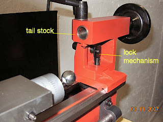
The tailstock went on easily after I put the lock back in place. This tailstock has a mechanism to lock it in place on the bed. (pic 603)
The three jaw chuck went on the head end. Easy to do. (pic 604)
After just nine hours of effort the lathe was all together and even ran properly. (pic 606).

Here is a close up of the controls (pic 607). What you don't see is the electronics inside this cover. That was the easiest part of the assembly because I am familiar with electricity and put the wires on right the first time. The plastic piece which is added after the wires and keeps them out of the lead screw was one of those things that three hands can do better than two. It helps a lot to have magnetized screw drivers so the little screws stay around when it is time to put them back on the machine.

This lathe even has a DRO (digital read out) for the spindle speed. A nice touch. (pic 608).

Would I do this again? Yes. Only I could do it much faster since now I know what the parts are. Next goal? Upgrade it, of course. I am going to change the tool post for a very nice quick change tool post from Little Machine Shop. It is made by A2Z company. That is another story…
Tractor Boy


